The Annotated Phase-Field Solver
An educational walk-through of phase-field fracture and the care required when building differentiable solvers in PyTorch.
A phase-field fracture solver is a strange object. It is a finite-element PDE solver, an optimisation routine, a non-smooth variational problem, and — when you write it in PyTorch — an end-to-end differentiable function of every input. Each of those framings is on its own a small PhD’s worth of material.
This post is the version of the explainer I wish I had three years ago. Each piece of math gets one figure, one code block, and one paragraph of why-it-is-the-way-it-is. By the end you should understand why a phase- field solver looks the way it does, what’s hard about turning one into a PyTorch module, and why differentiability changes what you can do with one.
The annotated walk-through format is inspired by Sasha Rush’s Annotated Transformer.
1. The thing we are modelling
A crack is a discontinuity in a continuum. That is the whole problem.
Classical fracture mechanics — Griffith, 1921 — frames crack growth as an energy bookkeeping exercise: a crack advances when the elastic strain energy released by its growth equals or exceeds the energy required to create new surface. The bookkeeping is exact, but it requires you to track a moving discontinuity. Numerically, that’s horrible. You need remeshing, level sets, branch detection, criteria for nucleation versus propagation, special elements at the tip — every one of which is its own decade of research.
Phase-field methods sidestep the whole apparatus by replacing the
discontinuity with a smooth scalar damage field d(x, t) ∈ [0, 1].
0 is intact material; 1 is fully cracked. Wherever d is high, the
material has effectively dissolved — its stiffness is multiplied by a
degradation function g(d) = (1 - d)².
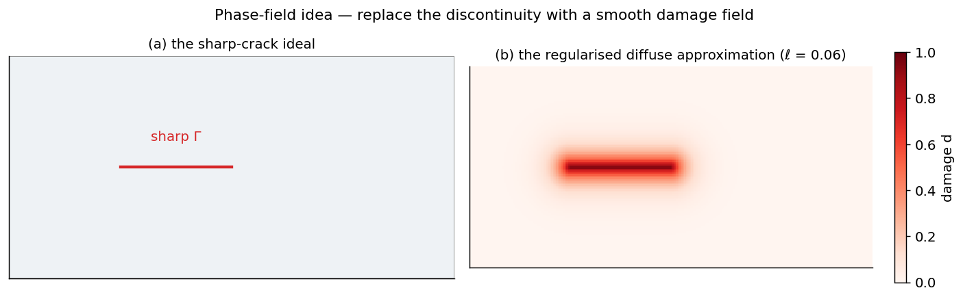
The regularisation length ℓ controls how diffuse the crack is. Smaller ℓ → sharper representation → finer mesh required. There is a Γ-convergence result (Ambrosio-Tortorelli, 1990; lifted to fracture by Bourdin, Francfort and Marigo, 2000) that says the phase-field functional converges as a variational problem to Griffith’s surface-energy functional as ℓ → 0. That theorem is the reason this whole field exists.
2. The energy functional, annotated
The variational form is
\[\mathcal{E}(u, d) = \underbrace{\int_\Omega g(d)\,\psi(\varepsilon(u))\,\mathrm{d}V}_{\text{degraded elastic energy}} + \underbrace{\frac{G_c}{c_w} \int_\Omega \left( \frac{w(d)}{\ell} + \ell\,|\nabla d|^2 \right) \mathrm{d}V}_{\text{surface (fracture) energy}}.\]Three blocks worth chewing on:
-
g(d) ψ(ε)is the elastic strain energy, degraded where there is damage.ψis the usual quadratic strain energy density from linear elasticity.g(d) = (1 - d)²is the standard choice; it has the rightg(0) = 1,g(1) = 0, andg'(1) = 0to avoid stress concentration at fully-damaged points. -
w(d)/ℓis the dissipation density per unit damage. The choicew(d) = dgives the AT1 model (compact support, an actual elastic region before damage onset).w(d) = d²gives AT2 (smooth, exponential profile, no elastic limit — damage initiates the moment load is applied).c_wis a normalising constant chosen so the total surface energy of a fully-formed crack equalsG_c × (crack length). -
ℓ |∇d|²is the gradient term that makes the regularisation work. Without it,dwould degenerate to a delta function. With it, the optimal damage profile around a crack is a smooth band of width proportional to ℓ.
The two analytical profiles fall out of a 1D Euler-Lagrange calculation:
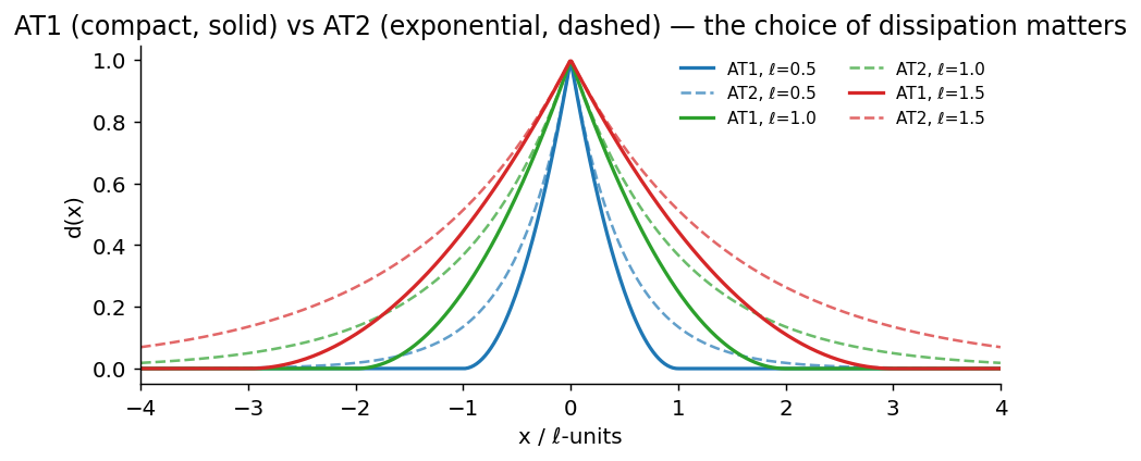
d*(x) = (1 - |x|/2ℓ)² for |x| < 2ℓ, zero outside. AT2: d*(x) = exp(-|x|/ℓ). Note the AT1 profile is compactly supported; outside the damaged band the material is truly intact. AT2 leaks damage everywhere.Drag the slider below to feel how ℓ controls width:
3. The discrete problem
The continuous energy is unhelpful for a computer. We discretise:
- Mesh the domain. Linear triangles or bilinear quads are a useful starting point; the appropriate discretisation still depends on the material model, regularisation length, and verification target.
ulives on the nodes as a vector field (dim × n_nodes degrees of freedom).dlives on the nodes as a scalar field (n_nodes DOFs).- The energy becomes a function of two big vectors:
E(U, D).
The variational principle says the solution (U, D) is a joint
minimiser of E. We almost never minimise jointly — the problem is
non-convex in (U, D) together but separately convex in each. So
practitioners use alternating minimisation:
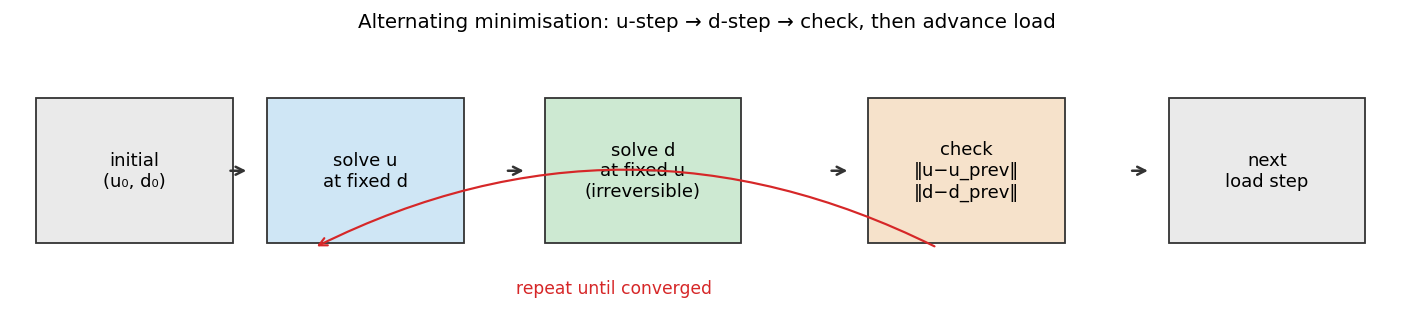
(u, d) has converged for the current load. Then advance load and start over.The two key constraints on the d-step:
- Box constraint:
d ∈ [0, 1]pointwise. - Irreversibility:
d(t + Δt) ≥ d(t)pointwise. Damage cannot heal.
The second one matters enormously. The first time you skip it because “it’s just a small Δt” your solver will silently produce thermodynamic nonsense.
4. The 80-line PyTorch sketch
The following is an illustrative 1D bar in tension. It makes the alternating structure visible, but it is not a production solver: it uses penalty boundary conditions and gradient-descent updates where a research code would normally use verified discretisation, linear algebra, and convergence controls.
import torch

# Mesh, parameters
N, L = 121, 1.0
xs = torch.linspace(0, L, N)
dx = float(xs[1] - xs[0])
E0, Gc, ell, cw = 100.0, 1.0, 0.04, 8/3  # AT1 normaliser

# State tensors for the illustrative updates below
u = torch.zeros(N, requires_grad=True)
d = torch.zeros(N, requires_grad=True)

def energy(u, d, u_app):
    # Element strain (constant per cell)
    eps = (u[1:] - u[:-1]) / dx
    d_e = 0.5 * (d[:-1] + d[1:])         # element damage
    g = (1.0 - d_e) ** 2                  # degradation
    psi = 0.5 * E0 * eps ** 2             # elastic density
    elastic = (g * psi * dx).sum()

    grad_d = (d[1:] - d[:-1]) / dx
    surface = (Gc / cw) * ((d_e / ell + ell * grad_d ** 2) * dx).sum()

    # Dirichlet BC penalty (illustrative; in a real solver these
    # are enforced by removing rows/cols from the linear system)
    bc = 1e4 * (u[0] ** 2 + (u[-1] - u_app) ** 2)
    return elastic + surface + bc

# Alternating-minimisation sketch: fixed iteration counts are illustrative.
d_prev = d.detach().clone()
for u_app in torch.linspace(0, 0.04, 50):
    for k in range(40):                  # u-step (fixed d)
        if u.grad is not None: u.grad.zero_()
        E = energy(u, d.detach(), u_app)
        E.backward()
        with torch.no_grad(): u -= 1e-4 * u.grad

    for k in range(40):                  # d-step (fixed u, irreversibility)
        if d.grad is not None: d.grad.zero_()
        E = energy(u.detach(), d, u_app)
        E.backward()
        with torch.no_grad():
            d_new = torch.clamp(d - 0.05 * d.grad, 0.0, 1.0)
            d_new = torch.maximum(d_new, d_prev)  # irreversibility
            d.copy_(d_new)
    d_prev = d.detach().clone()
That is the basic alternating structure. Research solvers use related staggered or monolithic formulations, but differ in their constitutive assumptions, boundary-condition treatment, nonlinear algorithms, convergence criteria, and mesh strategies. The compact example above is a map of the ingredients, not a replacement for those codes.
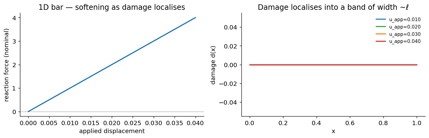
The toy version above produces this:
5. What’s hard about putting this in PyTorch
This is where most people get hurt. A short, opinionated list.
Non-smooth derivatives matter. The d-step gradient passes through
(1 - d)² ψ(u), and the u-step gradient passes through
(1 - d)² ψ(u) again. Both are smooth. But if you ever introduce a
spectral split (Miehe et al., 2010) to prevent crack-closure in
compression, you have max(0, ε⁺) · max(0, ε⁻) terms whose derivatives are
non-smooth at eigenvalue crossings. Automatic differentiation can still
provide derivatives away from those points, but the resulting nonlinear
iterations and sensitivities need careful numerical checks.
Irreversibility breaks the variational structure. The constraint
d(t+Δt) ≥ d(t) is a hard inequality, not part of the energy. You
enforce it either via projection (what the 80-line sketch above does)
or via a history variable (Miehe, 2010, which converts the inequality
into an extra term in the energy). The projection approach is simpler
but biases the gradient — the cells where the projection is active
have zero descent direction for further damage growth, so your line
search sees a kink. Production codes use projected-gradient or
active-set methods.
Stability under explicit dynamics. Dynamic fracture formulations may use explicit updates for mechanics together with a separate damage solve. The stable time increment and coupling behaviour depend on the chosen scheme, damage model, mesh, and loading. They should be verified on the intended benchmark rather than inferred from an elastic CFL estimate alone.
requires_grad semantics inside a load loop. Unrolling every update can
retain a large computational graph and become memory-intensive. Detaching
states controls that memory cost, but also changes which sensitivities are
available. Checkpointing and implicit-differentiation approaches are possible
alternatives, with assumptions that must be stated explicitly for each method.
6. What differentiability buys you
PyTorch makes it possible to differentiate through the operations retained in the computational graph. That does not make every formulation smoothly differentiable: projections, active constraints, convergence tolerances, and detached states all determine which sensitivities are meaningful. A useful differentiable solver documents those choices and verifies the gradients it uses.
Sensitivity boundary in this article. The toy sketch above illustrates unrolled automatic differentiation through the operations it retains. It does not implement an implicit-function-theorem or active-set adjoint, and its projected and detached updates should not be read as globally smooth gradients. The PhAST documentation and evidence summary are the appropriate references for the implemented public examples.
That single property is the door. Once it’s open, the material
parameters in the equation (G_c, E, ℓ) stop being constants and
become trainable. Pick any experimental measurement of a real
cracking specimen — a load-displacement curve from an Instron, a
digital-image-correlation displacement field, a crack trajectory from a
high-speed camera — and you can recover the material parameters that
would have produced that measurement:
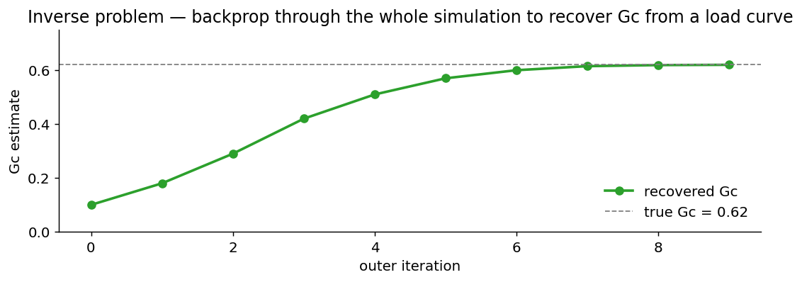
G_c from a load-curve mismatch. In a differentiable implementation, the chosen sensitivity route supplies a gradient to an outer optimiser; its validity should be checked for the formulation and constraints in use.The same simulation read two ways: a fracture mechanician calls it a forward solver (geometry + material → load curve); an applied-ML researcher calls it an inverse problem (load curve → material). Differentiability is what lets one piece of code be both.
The same modelling direction can support several research workflows:
- Gradient-based topology optimisation of toughened structures — design a part to maximise fracture resistance, not just stiffness.
- Hybrid learned assistance — train a model to propose a next damage field, while a physics-based audit and exact fallback retain solver authority.
- Differentiable digital twins — assimilate live sensor data into a phase-field simulation by gradient descent on initial conditions.
Each requires its own validation, data, and uncertainty treatment before it can support an engineering decision.
7. What’s actually hard (and where the field is going)
A short editorial.
-
Benchmarks. Fracture has valuable community reference problems, such as dynamic branching and Kalthoff-type impact cases, but cross-code comparison still depends heavily on stated material models, discretisation choices, loading, and observables. Better benchmark practice remains an open need.
-
Neural operators on PF data. Once you have a differentiable solver, generating large datasets is cheap. The hard part is the representation: damage fields are sparse and localised, which kills the spectral inductive bias of an FNO. Equivariant operators or graph-based architectures look more promising. See Mishra’s CIRM neural-operator lecture series for the theory.
-
Implicit-step differentiability. Differentiating through implicit PDE solves can use unrolling or implicit-function-theorem approaches. For fracture, active constraints and damage coupling make the numerical and modelling assumptions especially important.
-
Hybrid generalisation. A learned next-step damage proposal can overfit a single geometry or loading history. Held-out geometries, load paths, and audit/fallback behaviour should be part of its evaluation.
8. Where to go from here
If you want to build one of these yourself:
- Read the canon. Bourdin, Francfort & Marigo (2000), “Numerical experiments in revisited brittle fracture”, J. Mech. Phys. Solids 48(4). Miehe, Welschinger & Hofacker (2010), Int. J. Numer. Meth. Engng 83(10). These are the two papers that make every subsequent paper intelligible.
- Reference codes. Bourdin’s FreeFEM++ phase-field repo is the canonical implementation; Akantu has a maintained C++ phase-field module; PhaFiDyn is a validated explicit-dynamics FEniCS code worth reading end-to-end.
- My own work — PhAST is the public PyTorch-native, matrix-free phase-field fracture project associated with this material. Its documentation, source code, and preprint describe the implemented formulation and demonstrated examples.
If you want to use one without building it, start with the documentation and examples of an established code, then choose a formulation and verification case that match the question you need to answer.
If you read this far and have feedback or want to discuss differentiable solvers more generally, my email is in the site footer. I am especially interested in hearing about benchmark cases that should exist but don’t.
References
- Griffith, A. A. (1921). The phenomena of rupture and flow in solids. Philosophical Transactions of the Royal Society A 221(582–593), 163–198. doi:10.1098/rsta.1921.0006
- Francfort, G. A., & Marigo, J.-J. (1998). Revisiting brittle fracture as an energy minimization problem. Journal of the Mechanics and Physics of Solids 46(8), 1319–1342. doi:10.1016/S0022-5096(98)00034-9
- Bourdin, B., Francfort, G. A., & Marigo, J.-J. (2000). Numerical experiments in revisited brittle fracture. Journal of the Mechanics and Physics of Solids 48(4), 797–826. doi:10.1016/S0022-5096(99)00028-9 — the original phase-field-for-fracture paper.
- Ambrosio, L., & Tortorelli, V. M. (1990). Approximation of functionals depending on jumps by elliptic functionals via Γ-convergence. Communications on Pure and Applied Mathematics 43(8), 999–1036. doi:10.1002/cpa.3160430805 — the Γ-convergence guarantee that makes the whole field rigorous.
- Miehe, C., Welschinger, F., & Hofacker, M. (2010). Thermodynamically consistent phase-field models of fracture: Variational principles and multi-field FE implementations. International Journal for Numerical Methods in Engineering 83(10), 1273–1311. doi:10.1002/nme.2861 — the staggered scheme + history-variable formulation cited in §5.
- Borden, M. J., Verhoosel, C. V., Scott, M. A., Hughes, T. J. R., & Landis, C. M. (2012). A phase-field description of dynamic brittle fracture. Computer Methods in Applied Mechanics and Engineering 217–220, 77–95. doi:10.1016/j.cma.2012.01.008 — the dynamic-branching benchmark cases.
- Pham, K., Amor, H., Marigo, J.-J., & Maurini, C. (2011). Gradient damage models and their use to approximate brittle fracture. International Journal of Damage Mechanics 20(4), 618–652. doi:10.1177/1056789510386852 — the AT1 vs AT2 distinction.
- Akhare, D., Luo, T., & Wang, J.-X. (2025). Im-PiNDiff: Implicit physics-informed neural differentiable solver for stiff temporal systems. arXiv:2504.02260 — the implicit-step differentiability state-of-the-art cited in §7.
- Lu, L., Jin, P., Pang, G., Zhang, Z., & Karniadakis, G. E. (2021). Learning nonlinear operators via DeepONet. Nature Machine Intelligence 3, 218–229. arXiv:1910.03193
- Li, Z., Kovachki, N., Azizzadenesheli, K., et al. (2021). Fourier neural operator for parametric partial differential equations. ICLR 2021. arXiv:2010.08895
- Mishra, S. (2024). Learning operators — Lecture 1, CIRM Marseille. YouTube
- Rush, A. M. (2018). The Annotated Transformer. Harvard NLP. nlp.seas.harvard.edu — the explainer format borrowed for this post.
Related: PINNs tutorial — the data-vs-physics warm-up that this post extends. Cross-posted from the Tutorials series.